Fits & Limits
Engineering Tolerance (mm to inches and fit basics)
Convert the nominal dimension and its tolerance using the same exact factor. Dimensional fit, tolerance stack-up and process capability are separate checks.
Maintained by mmtoinches.im · Updated
NIST describes the standard inch as exactly equivalent to 25.4 mm
. NIST length definition. ISO 286-1 — tolerances, deviations and fits. Method and limitations.
Convert tolerances between mm and inches, compute hole/shaft limits, and classify fits as clearance, transition, or interference with straightforward formulas.
Conversion formulas
inches = mm ÷ 25.4
mm = inches × 25.4
Display inches to 4 decimals and mm to 3 decimals for tolerance work.
Quick tools
Use the mm to inches converter for nominal sizes and the fraction converter only for documentation; keep tolerances in decimal format to avoid rounding bias.
Tolerance and fit basics
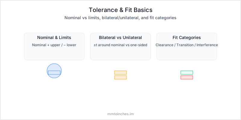
Nominal & limits
Nominal is the target size. Limits add upper/lower tolerance to define the allowed range.
Bilateral vs unilateral
Bilateral: ±t around nominal. Unilateral: tolerance in one direction only (e.g., +0/−t).
Fit categories
Clearance (always gap), interference (always overlap), transition (can be either). Determined by min/max clearance.
Interactive fit calculator
Enter nominal sizes and tolerances. See limits, clearance range, conversion, and fit verdict.
Hole
Shaft
Limits (mm)
Hole min/max: 20.000 / 20.010
Shaft min/max: 19.970 / 19.980
Clearance
Min: 0.020 mm
Max: 0.040 mm
Converted to inches
Hole min/max: 0.7874 / 0.7878 in
Shaft min/max: 0.7862 / 0.7866 in
Clearance
Min: 0.0008 in
Max: 0.0016 in
Verdict
Clearance fit
Tip: Maintain tolerance bandwidth during unit conversion (convert limits, not just nominal). Document decimal places (3 for mm, 4 for inches) in drawings.
Sample fit calculation
Hole vs shaft with mixed tolerances, converted to both units.
Inputs (mm)
Hole nominal: 20 mm; tol +0.01 / −0
Shaft nominal: 19.98 mm; tol +0 / −0.01
Limits (mm)
Hole min/max: 20.000 / 20.010
Shaft min/max: 19.970 / 19.980
Converted to inches
Hole min/max: 0.7874 / 0.7878 in
Shaft min/max: 0.7862 / 0.7866 in
Clearance
Min: 0.020 mm (0.0008 in)
Max: 0.040 mm (0.0016 in)
Verdict
Clearance fit
This is a simplified example. For critical assemblies, reference ISO 286 or ANSI B4.1 tables and confirm with inspection data.
Fit Classification Method
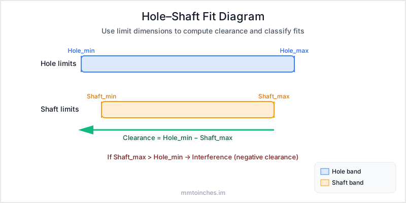
Use limit dimensions to compute clearance range and determine fit type.
Limits
- Hole_min = nominal − lower
- Hole_max = nominal + upper
- Shaft_min = nominal − lower
- Shaft_max = nominal + upper
Clearance
- Clearance_min = Hole_min − Shaft_max
- Clearance_max = Hole_max − Shaft_min
Verdict
- Both clearance_min and clearance_max > 0 → Clearance fit
- Both < 0 → Interference fit
- Mixed signs → Transition fit
Note: Convert limits between mm and inches using 25.4. Avoid rounding nominal alone; preserve tolerance bandwidth.
Case Library
Three scenarios to practice fit determination with mm ↔ inches conversion.
Case A — Always clearance
Hole/Shaft with mixed tolerances
Case B — Always interference
Hole/Shaft with mixed tolerances
Case C — Transition window
Hole/Shaft with mixed tolerances
Standards & Selection Guidance
For critical parts, reference standards to select tolerance grades and fit systems.
ISO 286 (metric)
- Common hole/shaft fits: e.g., H7/h6 for general sliding fits.
- Select tolerance grades based on function, material, and process capability.
- Use tables for exact deviations; this page focuses on reasoning and conversion.
ANSI B4.1 (inch)
- Inch-based fit systems with corresponding tolerance classes.
- When converting units, specify decimals (4 places) and maintain limit bandwidth.
- Document fit intent clearly for machinists and inspectors.
Tip: Start with function and assembly requirements, then choose a fit system and verify process capability before locking tolerances.
Process Capability Snapshot
A process name alone does not establish achievable tolerance. Compare the drawing limits with measured process data for the actual material, size, equipment and inspection method.
Machining
- Milling/turning: evaluate the specific feature, tooling, setup and thermal conditions.
- Reaming/broaching: obtain feature-specific capability and inspection evidence.
- Grinding: verify form, surface and dimensional requirements independently.
Forming & Additive
- Injection molding: account for shrinkage, material, cavity and conditioning.
- Sheet-metal bending: distinguish material thickness, bend angle and accumulated dimensions.
- 3D printing: verify orientation, material, calibration and post-processing.
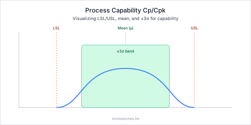
Cp compares specification width with six process standard deviations. Cpk also considers how far the process mean is from each limit. These indices require suitable, stable process data; a unit conversion does not prove capability.
Tolerance Stack‑Up & Inspection Workflow
Compare worst‑case and RSS methods, then align measurement and documentation across units.
Stack inputs (mm)
- Bracket A: 10.000 mm; +0.020 / −0.010
- Spacer B: 2.000 mm; +0.010 / −0.010
- Plate C: 5.000 mm; +0.030 / −0.020
Total nominal: 17.000 mm
Combined tolerance: +0.060 / −0.040 mm
Result
Min/Max (mm): 16.960 / 17.060
Min/Max (in): 0.6677 / 0.6717
Inspection tip: Record unit and decimals (mm ×3, in ×4). Translate acceptance criteria consistently between drawings and inspection reports.
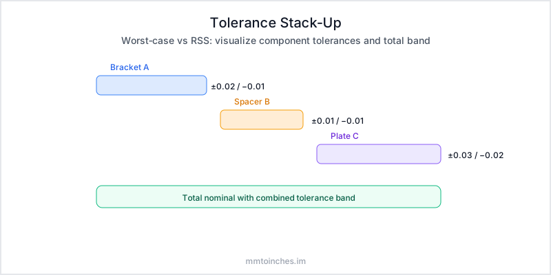
Note: Worst‑case is conservative; RSS assumes independent, normally distributed variations. Choose per quality strategy and risk tolerance.
Conversion How‑To
- Calculate limit dimensions from nominal and upper/lower tolerance for both hole and shaft.
- Convert limits between mm and inches using 25.4; keep tolerance bandwidth intact.
- Compute clearance range and classify the fit: positive → clearance; negative → interference; mixed → transition.
- Use 3 decimals for mm and 4 decimals for inches in tolerance work.
Frequently Asked Questions
Bilateral tolerance varies both above and below nominal (e.g., ±0.01 mm). Unilateral varies one way from nominal (e.g., +0/−0.02 mm).
Compute min/max limits for hole and shaft. Then clearance_min = hole_min − shaft_max and clearance_max = hole_max − shaft_min. If both are positive → clearance fit; both negative → interference; otherwise → transition.
No. Use ISO/ANSI tables for critical parts. The calculations here help you reason about fits and conversions, but manufacturing should follow the specified standard and inspection plan.
Use 3 decimals for millimeters and 4 decimals for inches in tolerance work unless your drawing standard specifies otherwise.
No, if you convert the limit dimensions correctly. Convert hole/shaft limits, then recompute clearance; the fit verdict remains consistent across units.
Use standards to select tolerance grades for precision parts (e.g., H7/h6). This page focuses on practical conversions and fit reasoning, not full tables.
Convert each feature’s limits, then combine using worst-case or statistical methods. Document the unit and precision to avoid rounding bias in inspection.
Avoid fractions for tolerance arithmetic. Use decimal formats for calculations; fractions are fine for documentation where required.
Convert and classify fits
Use the mm to inches converter for nominal sizes, keep tolerances in decimals, and document fit intent so machinists and inspectors stay aligned.
Sources and calculation notes
Convert the nominal dimension and its tolerance using the same exact factor. Dimensional fit, tolerance stack-up and process capability are separate checks.
Method: Divide millimeters by 25.4 to obtain inches. The factor is exact; displayed decimal values are rounded. Fractional inches are rounded to the selected denominator.
Scope: The calculators illustrate methods. Do not treat rounded values or fit examples as a complete ISO limit table or inspection certificate; consult the applicable drawing and standard.
Content maintained by mmtoinches.im. Updated and reference notes reviewed . How we calculate and present measurements. Sources support the stated definitions; examples and calculators are not certification of a product or compliance with a standard.